46 Results
View results:
Sort by:

Lateral-Torsional Buckling (LTB) is a phenomenon that occurs when a beam or structural member is subjected to bending and the compression flange is not sufficiently supported laterally. This leads to a combination of lateral displacement and twisting. It is a critical consideration in the design of structural elements, especially in slender beams and girders.
![Spans Based on Figure 5.2 from [1]](/en/webimage/039540/3493372/01_Abmessungen_EN.png?mw=640&hash=a3c436931baff3514db261b2d11bfa39abae9170)
In order to correctly design a downstand beam or a T-beam in RFEM 6 using the Concrete Design add-on, it is essential to determine the flange widths for the rib members. This article describes the input options for a two-span beam and the calculation of the flange dimensions according to EN 1992-1-1.

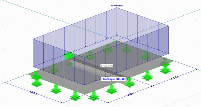
In many frame and truss structures, it is no longer sufficient to use a simple member. You often have to consider cross-section weakenings or openings in solid beams. In such cases, you can use the "Surface Model" member type. It can be integrated into the model like any other member and offers all the options of a surface model. The present technical article shows the application of such a member in an existing structural system and describes the integration of member openings.

The Steel Joist Institute (SJI) previously developed Virtual Joist tables to estimate the section properties for Open Web Steel Joists. These Virtual Joist sections are characterized as equivalent wide-flange beams which closely approximate the joist chord area, effective moment of inertia, and weight. Virtual Joists are also available in the RFEM and RSTAB cross-section database.

According to EN 1992-1-1 [1], a beam is a member of which the span is no less than 3 times the overall section depth. Otherwise, the structural element should be considered as a deep beam. The behavior of deep beams (that is, beams with a span less than 3 times the section depth) is different from the behavior of normal beams (that is, beams with a span that is 3 times greater than the section depth).
However, designing deep beams is often necessary when analyzing the structural components of reinforced concrete structures, since they are used for window and door lintels, upstand and downstand beams, the connection between split-level slabs, and frame systems.

In accordance with Sect. 6.6.3.1.1 and Clause 10.14.1.2 of ACI 318-19 and CSA A23.3-19, respectively, RFEM effectively takes into consideration concrete member and surface stiffness reduction for various element types. Available selection types include cracked and uncracked walls, flat plates and slabs, beams, and columns. The multiplier factors available within the program are taken directly from Table 6.6.3.1.1(a) and Table 10.14.1.2.

Besides the standardized gamma method, you can display the semi-rigid composite beams also as a framework model.

The automatic creation of combinations in RFEM and RSTAB with the "EN 1990 + EN 1991‑3; Cranes" option allows you to design crane runway beams as well as support loads on the rest of the structure.
Occasionally, it is necessary to consider in a model that some beams only lie loosely on top of one another without screwing or welding.
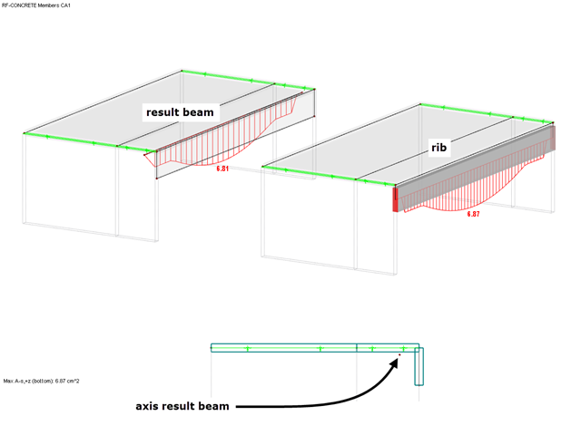
Although the design of downstand beams is usually carried out on a member model, a result beam can be used to perform the design on a model with only surfaces.

The new "Result Beam" member type in RFEM 5 allows you to determine the load sums of individual floors easily. To do this, model a member in the relevant floor or in all floors, then specify the relevant walls as inclusive objects in the parameters of the result beam. RFEM then integrates the surface internal forces into member internal forces.
This time, we will look at modeling downstand beams using ribs.

In timber design, beams are often built from several timber elements. The individual elements can be connected with glue, nails, bolts, or dowels. A glued connection is to be assumed as rigid. In the case of dowel‑type fasteners, the joint is compliant (slip joint), and the cross‑section properties of the connected elements cannot be fully applied.

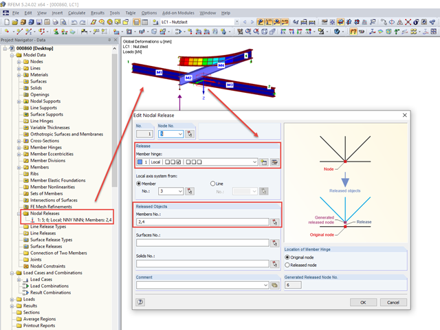
For cross‑laminated structures with large spans, downstand beams or hybrid structures are often used. They can be modeled in RFEM 5 by using surfaces and member cross‑sections. In both structural systems, curved downstand beams are also possible without any problems. In the case of the curved surface, the member is always appropriately generated by means of the automatic member eccentricity with the thickness distance of the surface and the member. The downstand beam can also be connected flexibly by means of a line release.

Concrete on its own is characterized by its compressive strength. An important part of reinforced concrete is reinforcing steel, which contributes to both the compressive and the tension resistance of the concrete. Welded wire fabric is generally located in the tension areas of the beams or surface elements (hollow core ceiling, wall, shell) to transfer the tensile forces induced by external loading.

When defining the effective slab width of T-beams, RFEM provides the predefined widths that are determined as 1/6 and 1/8 of the member length. A more detailed explanation on these two factors is given below.

Slender bending beams that have a large h/w ratio and are loaded parallel to the minor axis tend to have stability issues. This is due to the deflection of the compression chord.
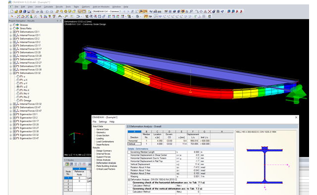
This article describes the different options for determining the allowable deformation of crane runway girders. Since multi-span beams and flexible lateral supports (sway bracing) are used in practice, this article will show how to select the correct method.
When performing control calculations and comparing the internal forces and the resulting required reinforcement of downstand beams, large differences can occur. Although the same load assumptions and spans are applied, some programs or the manual calculation display very different internal forces compared to the FEA model. The differences already occur in the case of the centric member and without considering the internal forces' components from the possible effective slab widths.

In accordance with Sec. 6.6.3.1.1 and Sec. 10.14.1.2 of ACI 318-14 and CSA A23.3-14, respectively, RFEM effectively takes into consideration concrete member and surface stiffness reduction for various element types. Available selection types include cracked and uncracked walls, flat plates and slabs, beams, and columns. The multiplier factors available within the program are taken directly from Table 6.6.3.1.1(a) and Table 10.14.1.2.

When designing steel columns or steel beams, it is usually necessary to carry out cross-section design and stability analysis. While the cross-section design can usually be performed without giving further details, the stability analysis requires further user-defined entries. To a certain extent, the member is cut out of the structure; therefore, the support conditions have to be specified. This is particularly important when determining the ideal elastic critical moment Mcr. Furthermore, it is necessary to define the correct effective lengths Lcr. These are required for the internal calculation of slenderness ratios.
From time to time, two intersecting beams overlap at a short distance. Such a structure raises the question, with regard to the modeling, of how it is possible to consider a contact with force transmission under compression between the two beams, while the contact under tension (for example, in case of a lifting top beam) should fail.

Fin plate connections are a popular form of pinned steel connection and are commonly used for secondary beams in steel structures. They can be used easily in beam structures arranged on the top edge (for example, working platforms). Manufacturing expenditures in the workshop as well as the onsite assembly costs are normally manageable. The design seems to be completed easily and quickly, but it has to be put into perspective to a certain extent in the following text. Moreover, this connection type is basically possible as a pinned beam-to-beam or pinned beam-to-column connection; the former case is the more common one in design practice.
Since the ultimate limit state of beams in the area of openings is affected, particular attention should be paid to this. In general, small openings can be sufficiently covered by adapting the beam structure to the openings. For big openings, it is necessary to consider and model the area separately.

This example is described in technical literature [1] as Example 9.5 and in [2] as Example 8.5. A lateral-torsional buckling analysis must be performed for a principal beam. This beam is a uniform structural member. Therefore, the stability analysis can be carried out according to Clause 6.3.3 of DIN EN 1993‑1‑1. Due to the uniaxial bending, it would also be possible to perform the design using the General Method according to Clause 6.3.4. Additionally, the determination of the critical load factor is validated with an idealized member model in line with the method mentioned above, using an FEM model.
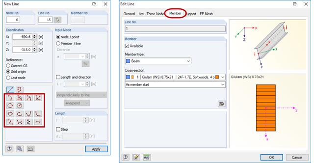
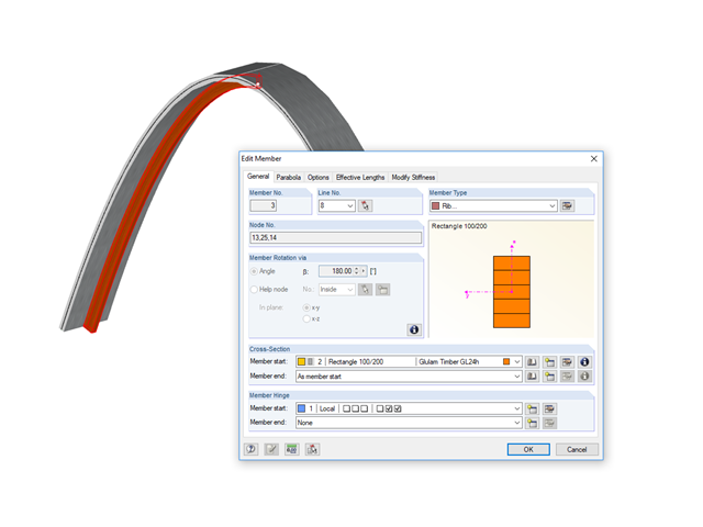
RFEM offers the possibility to model also curved beams. To do this, a curved line must be created first (see Figure 01). This line can then be assigned a beam with a cross-section. The advantages over modeling with beam segments are easier handling during the modeling, as well as a clearer result output of the internal forces.
The efficient design of prestressed structural components requires a few additional steps that go beyond the standard reinforced concrete design, from modeling tendons to the calculation of equivalent loads to the cross-section resistance design. Therefore, it is important that the software for prestressed concrete design is structured and the navigation is possible in the program. RFEM with two add-on modules RF-TENDON and RF-TENDON Design fulfills these requirements and allows engineers to carry out the complete design of prestressed beams, frames, plates, buildings and bridges according to EN 1992-1-1 with National Annexes and SIA 262.
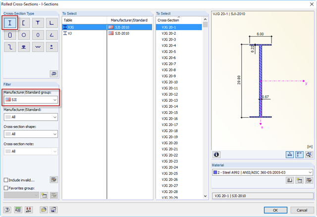
The Steel Joist Institute (SJI) previously developed Virtual Joist tables to estimate the section properties for Open Web Steel Joists. These Virtual Joist sections are characterized as equivalent wide-flange beams which closely approximate the joist chord area, effective moment of inertia, and weight. Virtual Joists are also available in the RFEM and RSTAB cross-section database.
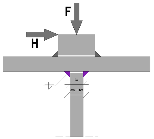
At the end of the topic on the design of welds on runway beams - after the technical articles about the rail weld seam in the ultimate limit state and the limit state of fatigue - a technical article about web fillet welds now follows. Both the ultimate limit state and the fatigue limit state are considered.
![Formula Symbols for Connection Between Chords and Web (Source: [1])](/en/webimage/009346/2418256/01-en-3-png.png?mw=640&hash=7a1bc6e87da6f5aeb6d26a130c6ca3dfb6edb8a4)
In order to ensure the effects of panels, which should act as tensile or compression chords, it is necessary to connect them to the web in a shear-resistant manner. This connection is obtained in a similar way as the shear transfer in the joint between concreting sections by using the interaction between compressive struts and ties. In order to ensure the shear resistance, it must be verified that the compressive strut resistance is given and the tie force can be absorbed by the transverse reinforcement.